

Avionics
BPS has produced a lot of rocketry flight computers. Like maybe way too many. Here they are in chronological order.
Fetch 1

Technically the second flight computer, the first was a series of jumper wires and a solder-less breadboard. After use in Scouts V0.4 through V0.7, the computer was retired and used for spare parts. Around March 2016, the computer was modified to use a new MCU after the Fetch flight software exceeded the capabilities of the ATmega32U4.
- Status: Scrapped for parts
- In service: Jan 2016 - May 2016
- Software: FETCH_1.8 - FETCH_2.7
- MCU: Atmel ATmega32U4/ATmega2560
- IMU: ST LSM9DS0
- Baro: Bosch BMP180
- Power: Canon LP-E6
- No pyro channels
- Outputs: XY TVC
Fetch 2


Fetch 2, if you can believe it from those photos, was built to be a safer and more powerful version of Fetch 1. In the photos, the Teensy 3.2 MCU is missing as this computer was also scrapped for parts after being retired. The computer carried 2 relay based pyro channels for the deployment of parachutes, drag fins, etc. During its life, both the IMU and flight batteries were switched, both for reliability reasons. Connections to the rocket were made through the large header sets on the top and bottom of the computer.
- Status: Scrapped for parts
- In service: May 2016 - Feb 2017
- Software: FETCH_2.8 - FETCH 4.0
- MCU: Freescale/NXP MK20dx256
- IMU: ST LSM9DS0/Bosch BNO055
- Baro: Bosch BMP180
- Power: Canon LP-E6/11.1v LiPo
- 2 relay based pyro channels
- Outputs: XY TVC
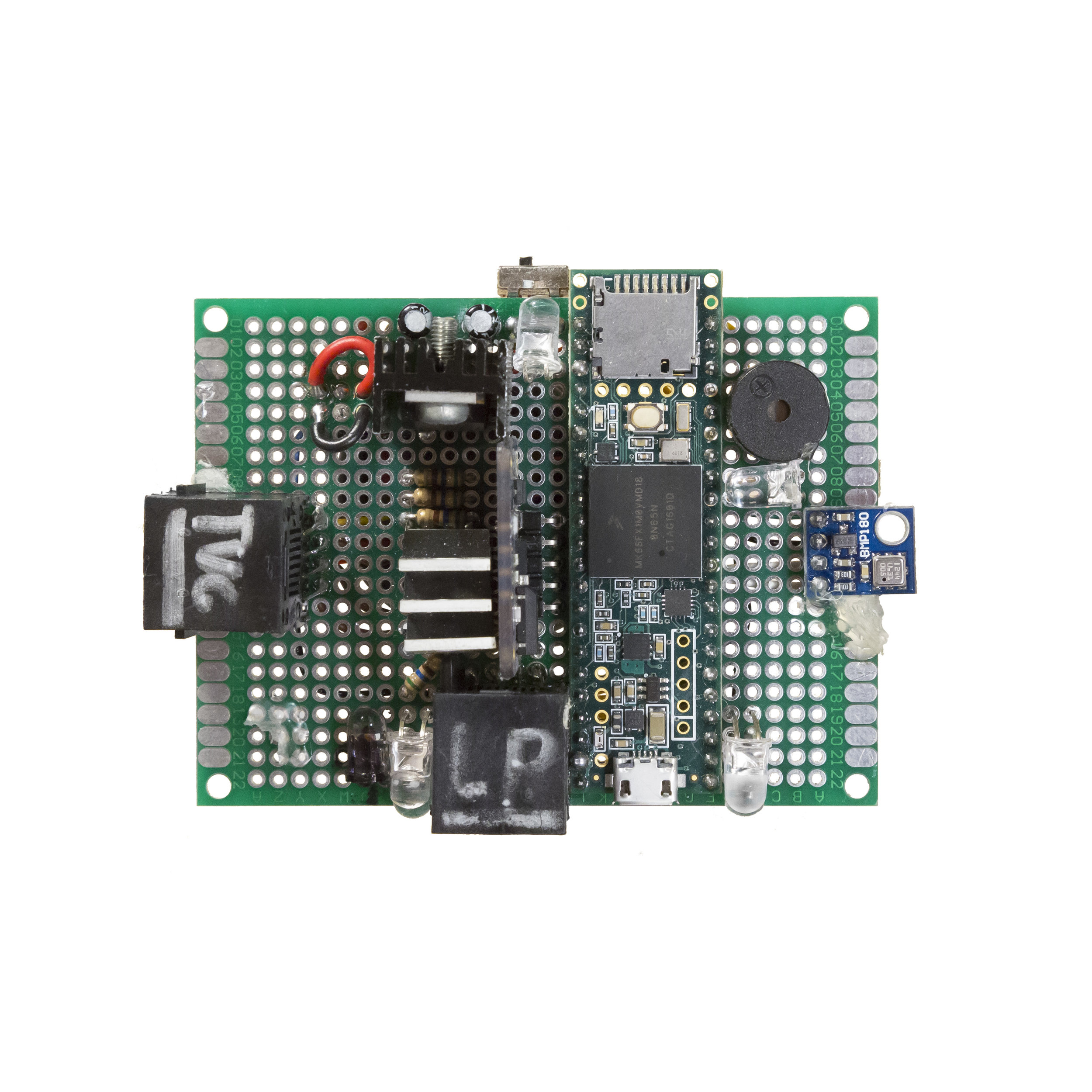
Relay


The Relay computer was built for a larger rocket. The original Relay rocket design was based on a 100mm airframe diameter and two gimbaled F class motors as ascent propulsion. The computer had comm inputs and outputs, labeled "LP" for the launch pad connection. TVC outputs and a separate barometer fixture were attached via the bottom two RJ45 jacks.
- Status: Fried MCU
- In service: Never flown
- MCU: Freescale/NXP MK66fx1m0vmd18
- IMU: Bosch BNO055
- Baro: Bosch BMP180
- Power: 11.1v LiPo
- 4 relay based pyro channels
- Outputs: XY TVC
Zener

Zener was largely a replacement for the fried Relay computer. The major differences included an onboard barometer, solid state pyro channels, and more LEDs. It was the last computer to feature a comm connection to the launch pad. The connection physically unreliable due to expansions and contractions in the plastic of the port in different climates.
- Status: Retired
- In service: Feb 2017 - April 2017
- Software: SIGNAL_0.1 - SIGNAL_1.1
- MCU: Freescale/NXP MK66fx1m0vmd18
- IMU: Bosch BNO055
- Baro: Bosch BMP180
- Power: Standard 9v
- 3 pyro channels
- Outputs: XY TVC
Vector 1.2
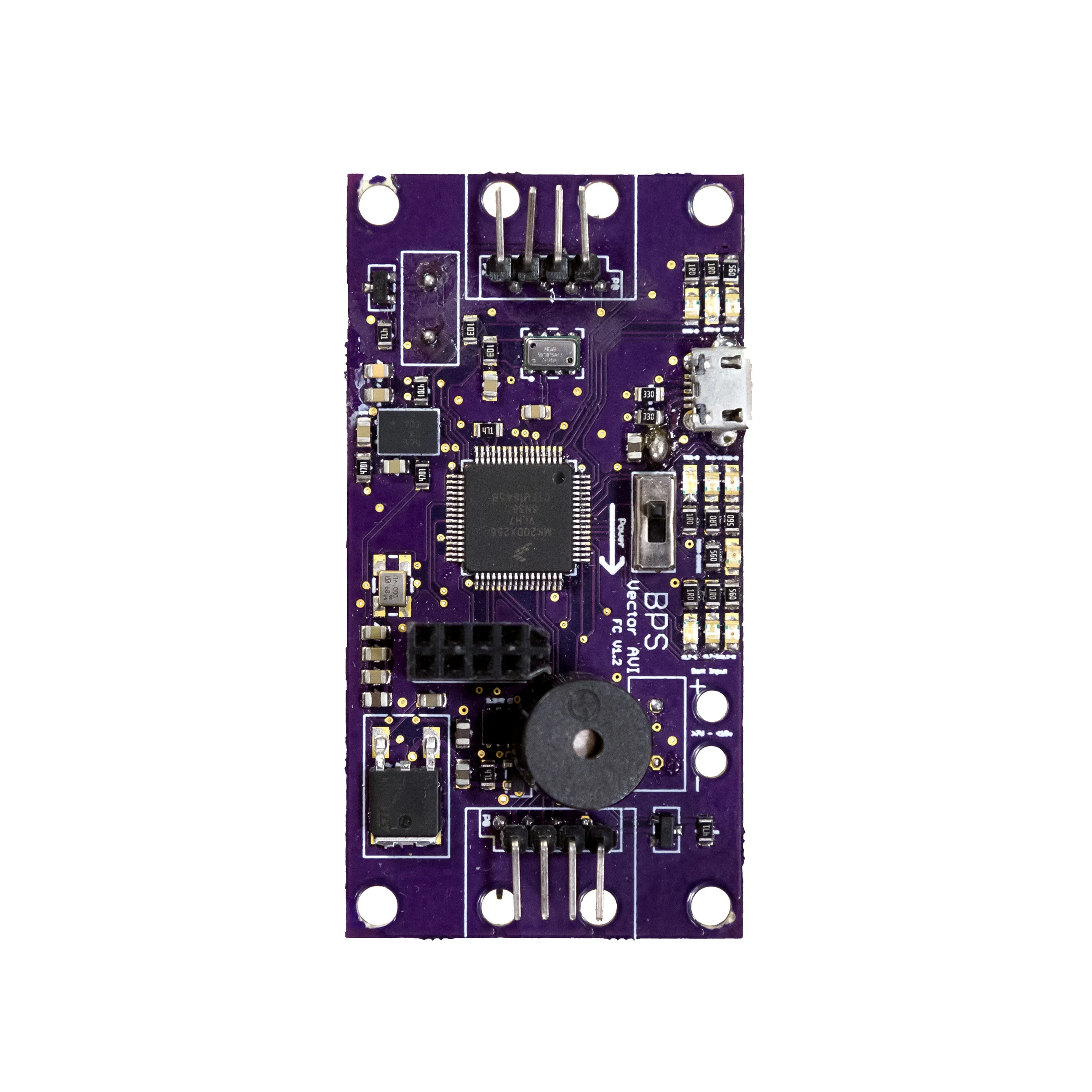

Vector 1.2, later renamed Signal, was the first version of the Signal Avionics family of flight computers. It was also the first printed circuit board designed by BPS. Featuring a breakout PCB to be mounted on the TVC motor sleeve, the avionics package had active TVC feedback for total closed-loop control. The lower header outputs were for TVC controls and feedback, the upper outputs for active fin control. The computer was used for several static fire tests, but never flown.
- Status: Retired
- In service: April 2017 - July 2017
- Software: SignalSoft 0.1.0 - 0.3.1
- MCU: Freescale/NXP MK20dx256
- IMU: Bosch BNO055
- Baro: TE MS5611
- Power: 7.4v LiPo
- 4 pyro channels
- Outputs: XY TVC, 4 Fins
Signal 1.3


Signal 1.3 was designed to be controlled via a screen with a few buttons attached. The output terminal can be seen just below the USB port. The idea was quickly killed as being a poor use of time. The decision was made to include Bluetooth functionality to later versions, meaning the screen would be replaced anyway. The computer flew several times, successfully testing many core functions of the Signal flight software.
- Status: Retired
- In service: July 2017 - October 2017
- Software: SignalSoft 0.3.2 - 0.6.5
- MCU: Freescale/NXP MK20dx256
- IMU: Bosch BNO055
- Baro: TE MS5611
- Power: 7.4v LiPo
- 4 pyro channels
- Outputs: XY TVC, 4 Fins
Signal 1.4


With the removal of fin outputs, the simplification of the PCB layout, and a few other improvements, Signal 1.4 was built to verify the design of Signal Alpha. Everything but a few changes to the silkscreen.
Fin outputs were ditched because the complexity of commercial active canards is far greater than that of TVC. The mechanics are fairly simple, the controls software is not. They also didn't fit BPS's mission to make model rockets more realistic.
- Status: Retired
- In service: October 2017 - November 2017
- Software: SignalSoft 0.6.6 - 0.8.2
- MCU: Freescale/NXP MK20dx256
- IMU: Bosch BNO055
- Baro: TE MS5611
- Power: 7.4v LiPo
- 4 pyro channels
- Outputs: XY TVC
Signal Alpha


The first commercial available TVC flight computer. Signal Alpha was produced in a small run during the fall of 2017. Users could interface with the computer via a configuration file on the root of Micro SD card. This technique is still used as a robust backup in more recent flight computers. While both black and white versions were produced, only white versions were sold. The black color scheme continues to be used as a testing platform for more experimental flight software, occasionally flying as a passive research payload on existing vehicles.
- Status: Active as test bed
- In service: November 2017 - present
- Software: SignalSoft 0.8.2 - 0.8.6
- MCU: Freescale/NXP MK20dx256
- IMU: Bosch BNO055
- Baro: TE MS5611
- Power: 7.4v LiPo
- 4 pyro channels
- Outputs: XY TVC
Signal R2(dev version)


Signal R2(dev) was the first version in the Signal family to carry Bluetooth functionality. It also served to both port the flight software from the ARM Cortex M4 to the better suited ARM Cortex M0 processor architecture. Plus NXP put a very very fun surprise 40+ week lead time on the processors used by Signal Alpha and before. Continuity detection was added to all pyro channels, which were reduced from 4 to 3 due to limited space and outputs. Several other circuitry modifications were made to keep the power structure more efficient. The PCB shown in the photos is kinda covered in soot from a rogue motor ejection, my apologies.
- Status: Retired
- In service: January 2018 - April 2018
- Software: SignalSoft 0.8.7 - 1.1.8
- MCU: Atmel ATSAMD21
- IMU: Undisclosed
- Baro: ST LPS22HB
- Power: 7.4v LiPo
- 3 pyro channels w/ continuity detection
- Outputs: XY TVC


Signal R2 is the latest revision in the Signal family. With upgrades in the barometer, continuity detection circuitry, power switch, Bluetooth antenna, and layout, it is the finest TVC flight computer that BPS has designed. A great deal of importance was placed on keeping Signal R2 aesthetically beautiful. All passive components were placed on the back in nearly identical orientation, silkscreen was limited to only the most vital labeling, and every component not important for proper use was removed. More details about Signal Avionics can be found by clicking here.
- Status: Active
- In service: April 2018 - present
- Software: SignalSoft 1.1.9+
- MCU: Atmel ATSAMD21
- IMU: Undisclosed
- Baro: Undisclosed
- Power: 7.4v LiPo
- 3 pyro channels w/ continuity detection
- Outputs: XY TVC

All BPS designed flight computers in chronological order